Home
Search
Reference Manuals
Return
Track Group Documentation
Users Manual for Program TRC_IPLAS2
Table of Contents
Introduction
Input data commands
Input data Example
Output data Example
Introduction
Program TRC_IPLAS2 is designed for translating track measurements made by
a Plasser&Theurer EM80 track measuring vehicle.
The EM80-car have 3 measuring axles for lateral measurements and 3 other axles
for vertical measurements.
The three axles measuring vertical irregularities are not equally spaced.
The advantage of not having the axles equally spaced, is that it is possible to reduce the number of zeros
in the measuring vehicle transfer function.
The input data file is read in free format, but
the columns in the file shall have the same contents as in
a SPL-file.
The output data file is written in trax_wdesign-format.
Since the transfer function of the track measuring car is low for
some waves lengths,
the transfer function back to Cartesian coordinates cannot be ideal,
it must be delimited.
The filtering takes place in program FTRANS, filter
IMAUZ and
IPLASSER.
See also:
| TRC_PLAS | Calculates versines of the columns in a track irregularity file |
Input data commands
Input data is read in free format, valid separators between the input values are <space>,
<comma>, <tab>, <equal sign> or <carriage return>.
The commands can be written both in lower and upper case letters.
The operation of the program is controlled by the commands
described below; some of the commands also need arguments.
CALC_QN
- Activate the calculation of QN-numbers according to UIC 518.
Computation time could be saved if calculation of QN-numbers are skipped.
Declared= Character*3 Default= yes
CREATE_PLOT
- Activate the generation of plots.
Computation time could be saved if generation of plots are skipped.
Declared= Character*3 Default= yes
DX
- Equidistant step between the interpolated points in the X-axis.
The FFT-algorithm in the backward transformation
requires that the points in input data have equidistant
distances in their X-axles.
Therefore the curves read from INFIL always
will be interpolated before any calculations takes place.
Declared= Real*4 Default= 0.5
INFIL
- File containing the track measurements written in *.spl-format.
However only the columns for short waves irregularities are used.
Declared= Character*132 Default= Blank
REMOVE_UCAT_WORK
- Command which controls if the working directory "ucat_work"
should be removed or not after the calculation.
Declared= Character*4 Default= 'NO'
QNUMB_SPEED
- Speed to be used when evaluating track quality.
Valid values are: 80, 120, 160, 200 and 300 [km/h].
Declared= Real*4 Default= 120 [km/h]
VEHICLE_DIRECTION
- 'A' If the A-end of the measuring-trolley is facing towards increasing kilometers of the track.
'B' If the B-end of the measuring-trolley is facing towards increasing kilometers of the track.
Declared= Character*1 Default= Blank
L_LATERAL_WAVES
- High pass filter cut-off frequency for lateral track irregularities.
Declared= Real*4 Default= 55.55 [m]
N_LATERAL_WAVES
- Order of the lateral high pass filter.
The filter is of type Butterworth in two stages.
First forward filtering then backward filtering.
This type of filtering avoids different delays for different waves.
N_LATERAL_WAVES must be an even number.
Declared= Integer*4 Default= 6
L_SHORT_WAVES
- Low pass filter cut-off frequency.
Track irregularities of very high frequencies can be measured in the STRIX track measuring car.
However too short waves in the track are not of interest, if the track is going to be used for
estimation of ride comfort and lateral track forces only.
The short waves makes simulation times longer,
because the integrate needs to make smaller time-steps.
Declared= Real*4 Default= 1.2 [m]
N_SHORT_WAVES
- Order of the low pass filter.
The filter is of type Butterworth in two stages.
First forward filtering then backward filtering.
This type of filtering avoids different delays for different wave lengths.
N_SHORT_WAVES must be an even number.
Declared= Integer*4 Default= 16
UTFIL
- File containing the output data, written in *.trax-format.
Declared= Character*132 Default= Blank
XSTART_KM
- Defines the first kilometer from where the translation shall begin.
Declared= Real*4 Default= -1000000
XSTART_M
- Defines the meter within the first kilometer from where the translation shall begin.
Declared= Real*4 Default= -1000
XSTOP_KM
- Defines the last kilometer where the translation shall end.
Declared= Real*4 Default= 1000000
XSTOP_M
- Defines the meter within the last kilometer where the translation shall end.
Declared= Real*4 Default= 1000
Input data Example
Following example: Master.trc_iplas2f can be used as a master file:
##
##      Input data for program TRC_IPLAS2
##

  VEHICLE_DIRECTION= A
  QNUMB_SPEED      = 120             # Valid speeds are 80, 120, 160, 200 and 300
  REMOVE_UCAT_WORK = yes

  L_SHORT_WAVES= 1.5
  N_SHORT_WAVES= 4

  CALC_QN    = yes
  CREATE_PLOT= yes

  XSTART_KM= -1000000  XSTART_M= -1000
  XSTOP_KM =  1000000  XSTOP_M =  1000

  INFIL= SPL-file.txt
  UTFIL= output.trax_wdesign
Output data example:
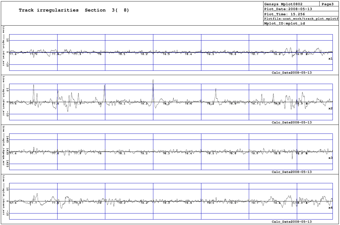
Y_mid-, z_mid-, gauge- and cant- errors:
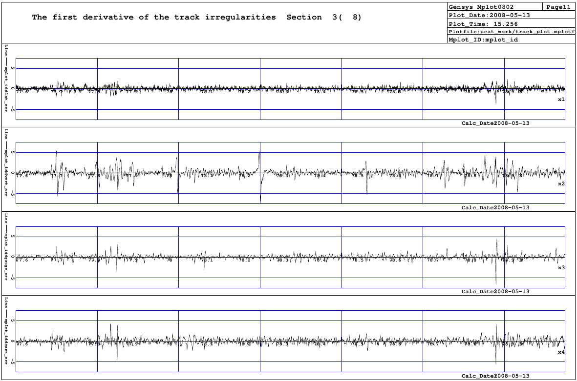
Derivative of the y_mid-, z_mid-, gauge- and cant- errors:
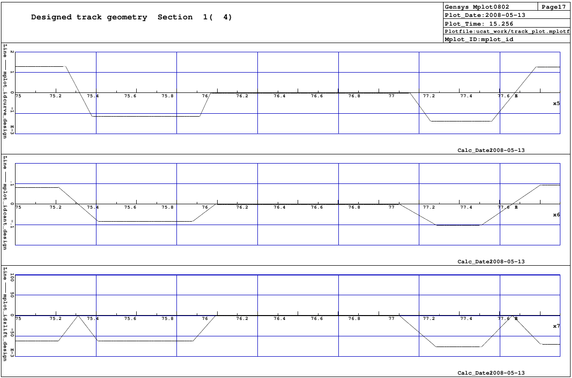
Designed track geometry:
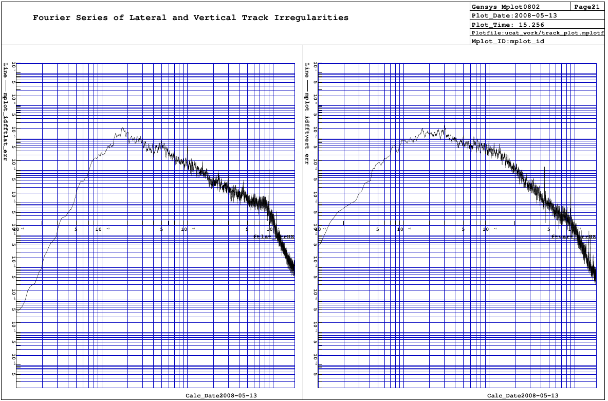
Fourier spectra of the y_mid- and z_mid- errors:
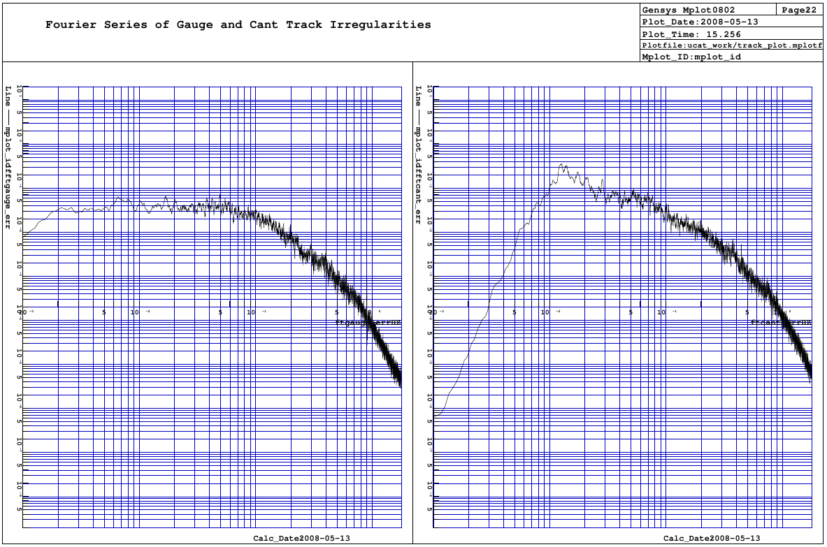
Fourier spectra of the gauge- and cant- errors: